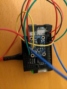
I ran into a problem with interfacing Adafruit’s BNO055 breakout board with a Raspberry Pi Zero W, and this led me down a rabbit hole or three regarding the Pi’s implementation of I2C and using CircuitPython on a Pi.
There are pieces of this information spread across the internet, but I figured I’d try to summarize it in one place in the hope it will help others.
I2C Clock Stretching Problems with Raspberry Pi’s
Many sensors and other devices use I2C for communicating with microcontrollers or microcomputers, such as an Arduino or Raspberry Pi. Like many, but not all, sensor devices, the BNO055 uses “clock stretching.” Clock stretching occurs when clock line (SCL) is held low after receiving (or sending) a byte, indicating that the device it is not yet ready to process more data. The primary that is communicating with it may not finish the transmission of the current bit, but must wait until the clock line actually goes high. Unfortunately, the chip that handles I2C communications on Raspberry Pi boards has a flaw and does not handle clock stretching properly. In my case, this was causing erroneous readouts. Because the flaw is in the hardware, it can’t be fixed via a software update, but there are workarounds. As of April 2021, there are some reports that this has been fixed on Raspberry Pi 4 boards, but anecdotal reports say it’s a problem even on these newest boards. If you’ve any experience with I2C clock stretching on Pi 4’s, leave a comment on what you’ve found.
While unneeded to work around the problem, you can read a lot more detail about the bug at Raspberry Pi I2C clock-stretching bug.
Workarounds
There are three basic ways to work around this issue: 1) lower the clock speed on the I2C bus so that the device won’t need to clock stretch, 2) Use software I2C rather than the build-in hardware with the flaw, or 3) if supported by your device, use another type of interface, such as SPI or UART interfaces.
Lowering the Clock Speed
First, of course, you want to be sure that you’ve enabled I2C communications on your Pi. You can read how to do so here: Enable I2C Interface on the Raspberry Pi.
Next you want to go into the config file and slow down the clock rate so that it’s less likely that clock stretching will be used. A typical default speed on a Pi is 100000, and it’s suggested in multiple locations on the net to slow it down to 10000. You can do that by adding
dtparam=i2c_arm_baudrate=10000
to your config.txt file. If you need help on how to do that, see this: I2C Clock Stretching. You’ll need to reboot for the change to take effect. If this doesn’t work, you can try slowing it down even further.
Software I2C
Raspberry Pi’s operating system includes support for software I2C which can be enabled by just a few lines in the config.txt file. Just add
dtoverlay=i2c-gpio,bus=3This will create an I2C bus called /dev/i2c-3. SDA will be on GPIO23 and SCL will be on GPIO24 which are pins 16 and 18 on the GPIO header respectively. For more information, see Configuring Software I2C on the Raspberry Pi.
Other Interfaces
Of course, if the device you are interfacing to supports other communications links, such as SPI or a UART interface, you may want to consider using them rather than the I2C interface.
UART Interfaces with CircuitPython and the Raspberry Pi
CircuitPython has become a very popular choice for writing code for microcontrollers, and can also be used on Linux boards, such as Rasberry Pi’s, to take advantage of the large and growing set of device libraries found in CircuitPython. Several of the libraries provide UART interfaces for boards supporting that interface. However the instantiation for the interface differs between Linux boards (including Raspberry Pi’s) and other boards without an operating system. For example, you may see code like this
# Use these lines for I2C
# i2c = busio.I2C(board.SCL, board.SDA)
# sensor = adafruit_bno055.BNO055_I2C(i2c)

# Use these lines for UART except Linux devices
uart = busio.UART(board.TX, board.RX)
sensor = adafruit_bno055.BNO055_UART(uart)
This works fine for non-Linux boards, but for Linux, the CircuitPython busio library is not used for UART interfaces. Instead, you need to import the Python serial library and assuming you have linked directly to the UART pins, the uart = line should be replaced with something like:
uart = serial.Serial("/dev/ttyS0", baudrate=9600, timeout=1000)
You can also use an external serial to USB convertor to link up your peripheral device and then use the USB port on your Pi. You can find more details at Adafruit’s CircuitPython on Linux and Raspberry Pi UART / Serial page.
Conclusion
If you’re planning a Pi project involving I2C, or have had problems with one in the past, I hope that this collection of information helps you sort things out and implement the best option for your project.
Please share any experiences you’ve had with I2C and Raspberry Pi’s in the comments.

